Amiga 1200+
About
This project is a re-implementation of the Amiga 1200 board started from the schematics.
I made some changes and enhancements to the original schematics.
Features
- All Original AA chips are needed and can be put into the sockets. These include Lisa, Paula, Alice, Gayle and the two CIA chips.
- Budgie being a TQFP package is soldered directly to the board.
- The keyboard controller has been replaced by a modern 8 bit MCU.
- Keyboard used to switch bootselector, set stereo separation and switch ROM banks.
- Because there are different Chip Ram configurations possible, the Chip Ram is moved to a separate board. (e.g. 1Mx4, 256Kx16 or 512Kx8 DRAM chips)
- Video output has been moved to a separate output board. This board get all Lisa output signals and also all the typical Zorro signals. This means that an RTG card can be developed.
- The PCMCIA slot has been removed and in the free space, a Compact Flash socket is located. This compact flash is connected to the IDE interface.
- The IDE interface is buffered using the otherwise unused Bus Buffer in Budgie.
- The power brick is replaced by an internal AC/DC power supply. This power supply is capable of:
- 5 Volts: main power rail 6 Amp capable
- 12 Volts: 1 Amp capable
- two PC standard 3 Pin fan headers are added to the board.
- An extra floppy power connector for powering ClockPort devices.
- An I2C controller has been added and there is a connector on board to connect I2C boards. (e.g. Real Time Clock modules)
- The I2C bus is also used to drive a DigiPot that is in the audio path, this is used to set the stereo separation of the Amiga Audio signals.
- Extension board connector for mouse/joystick/Network/Flash Floppy/Boot selector.
This project is Open Source: more on Bitbucket
I also post regular updates on Twitter: https://twitter.com/JeroenNumber42
Project history
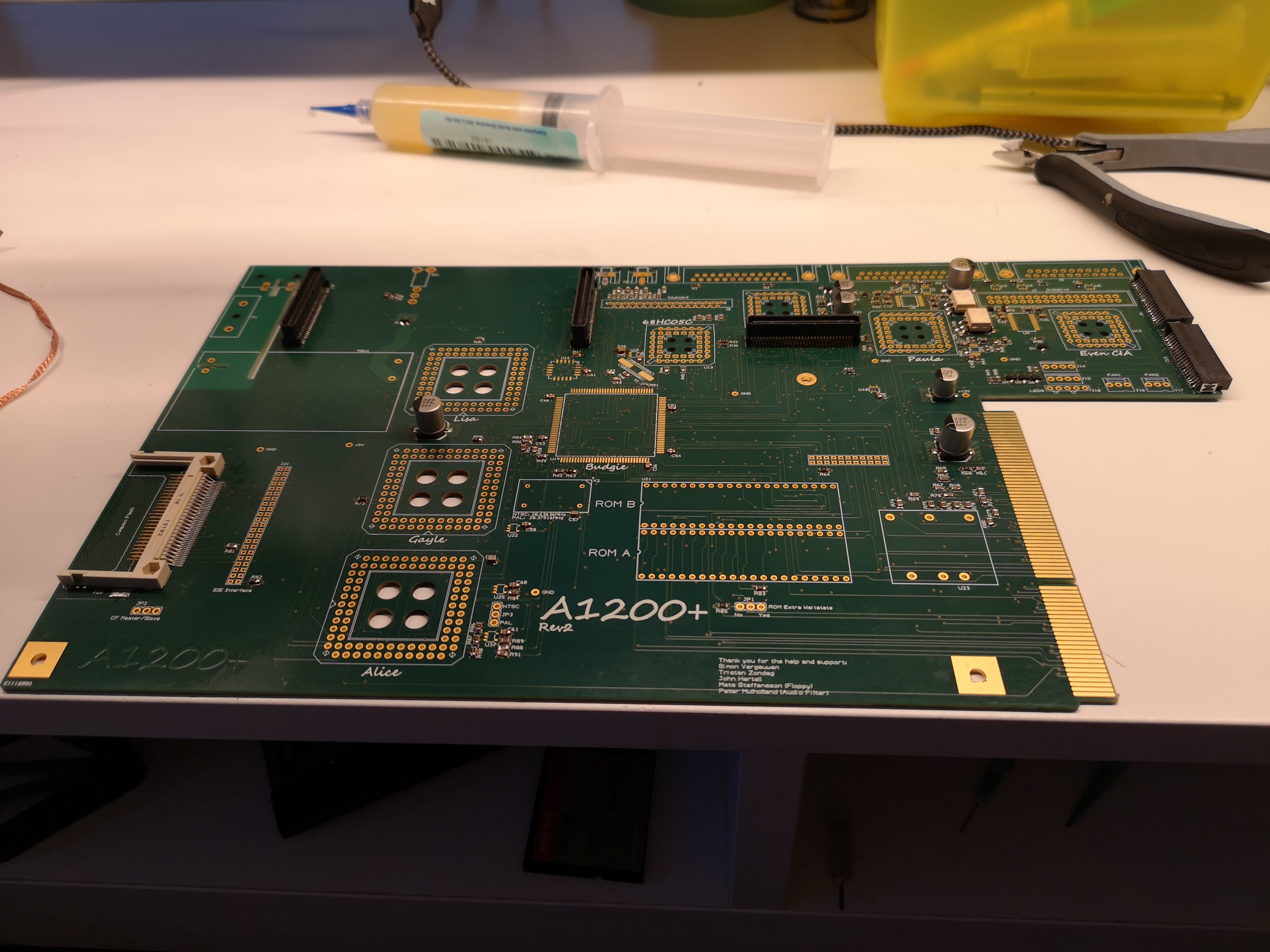
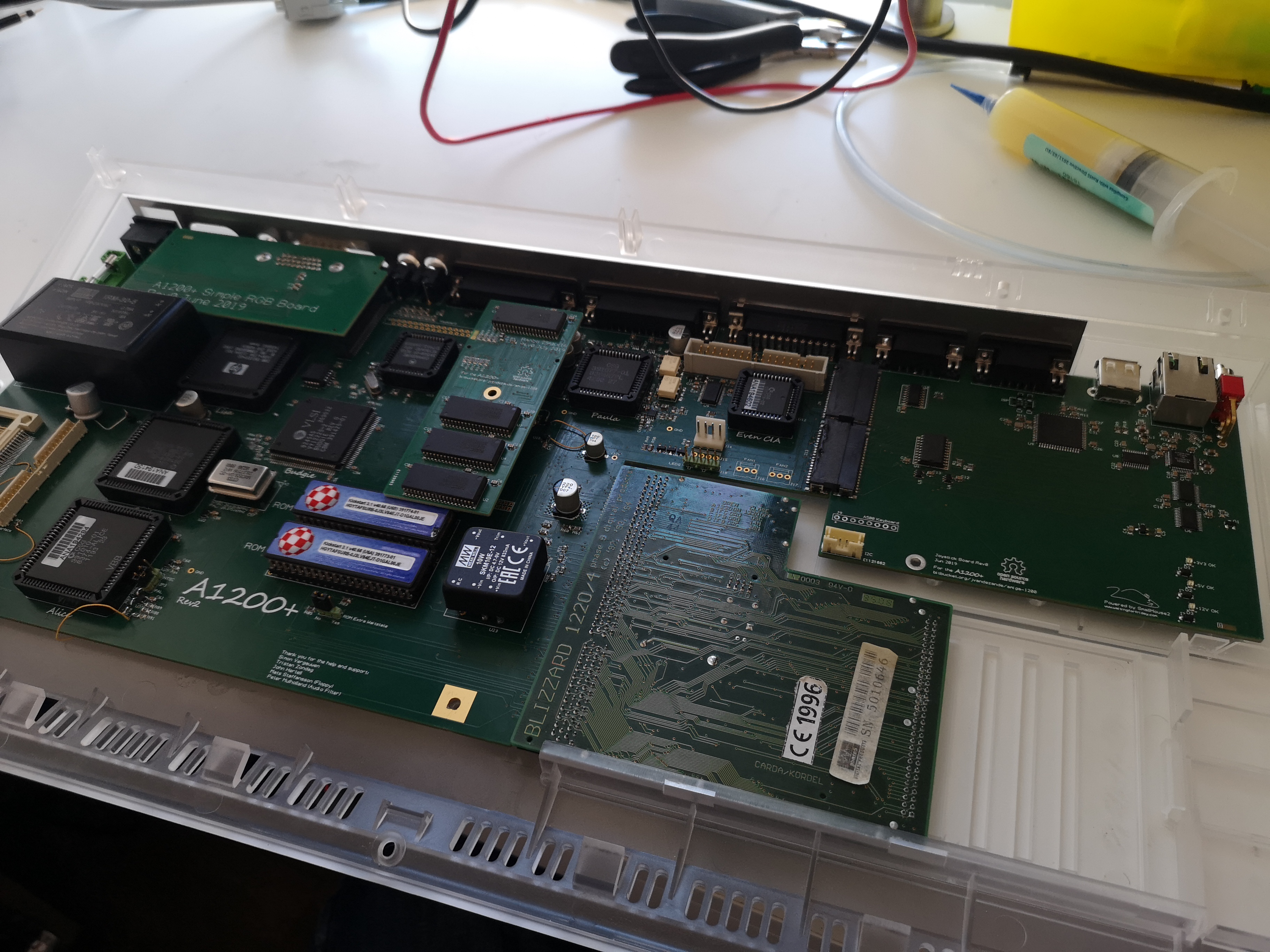
Rev2
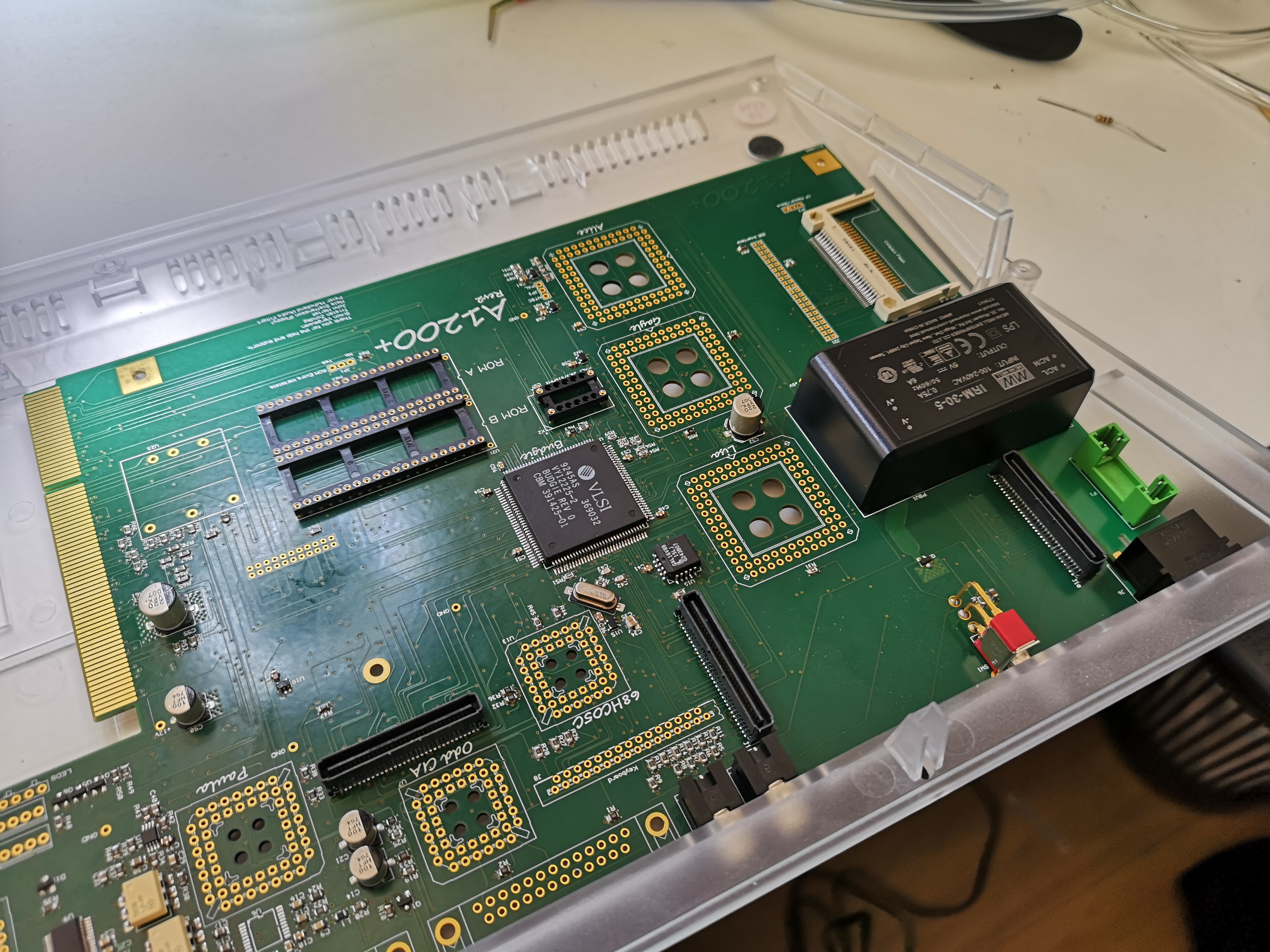
Here you can see Rev2 of the PCB with all the passives soldered.
Testing the clearance of the PSU under the keyboard.
Everything fits just fine under the keyboard and in the case.
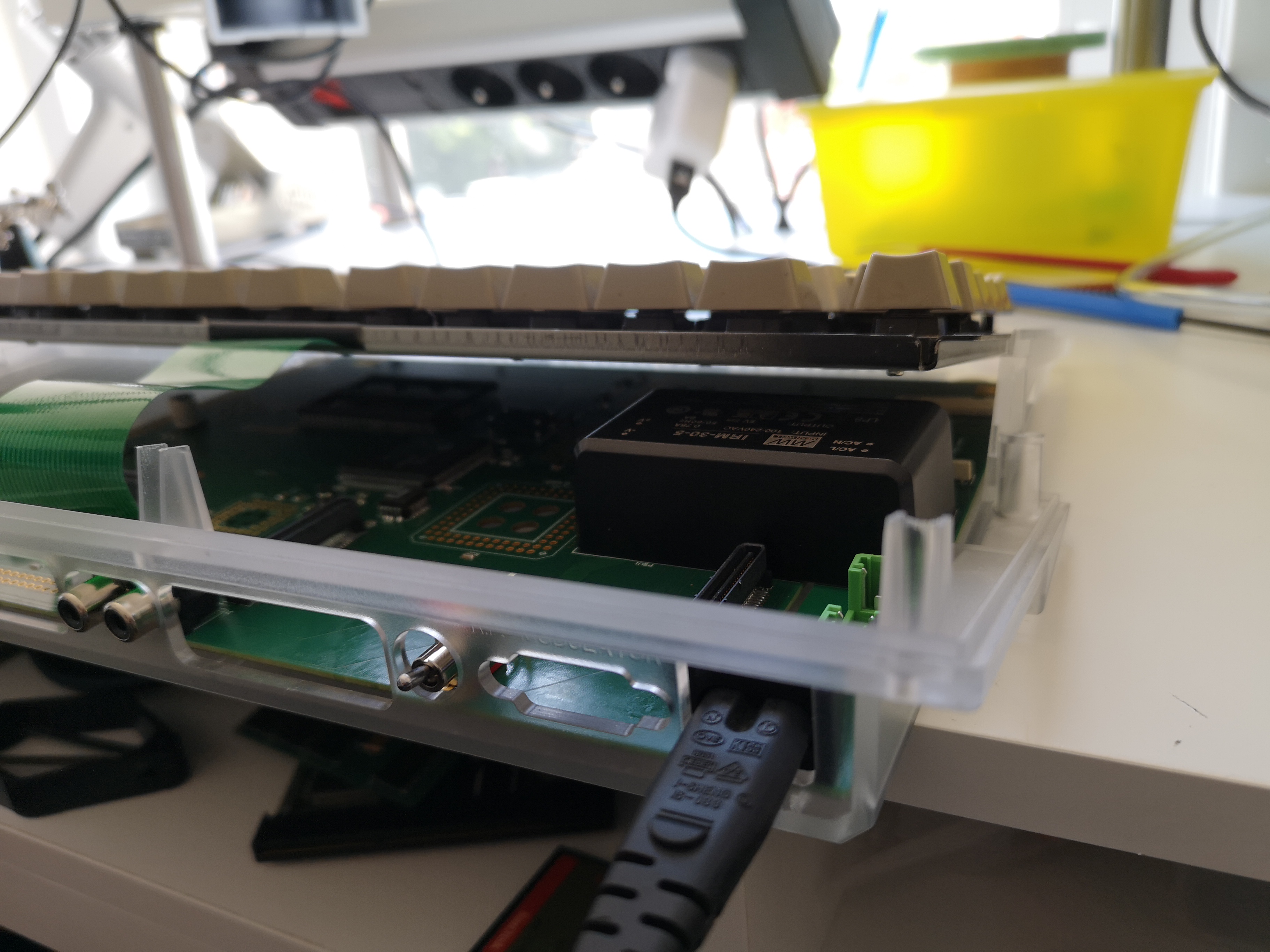
Here you can see the build-in PSU more clearly. It is a 30W PSU, so it supplies up to 6A@5V.
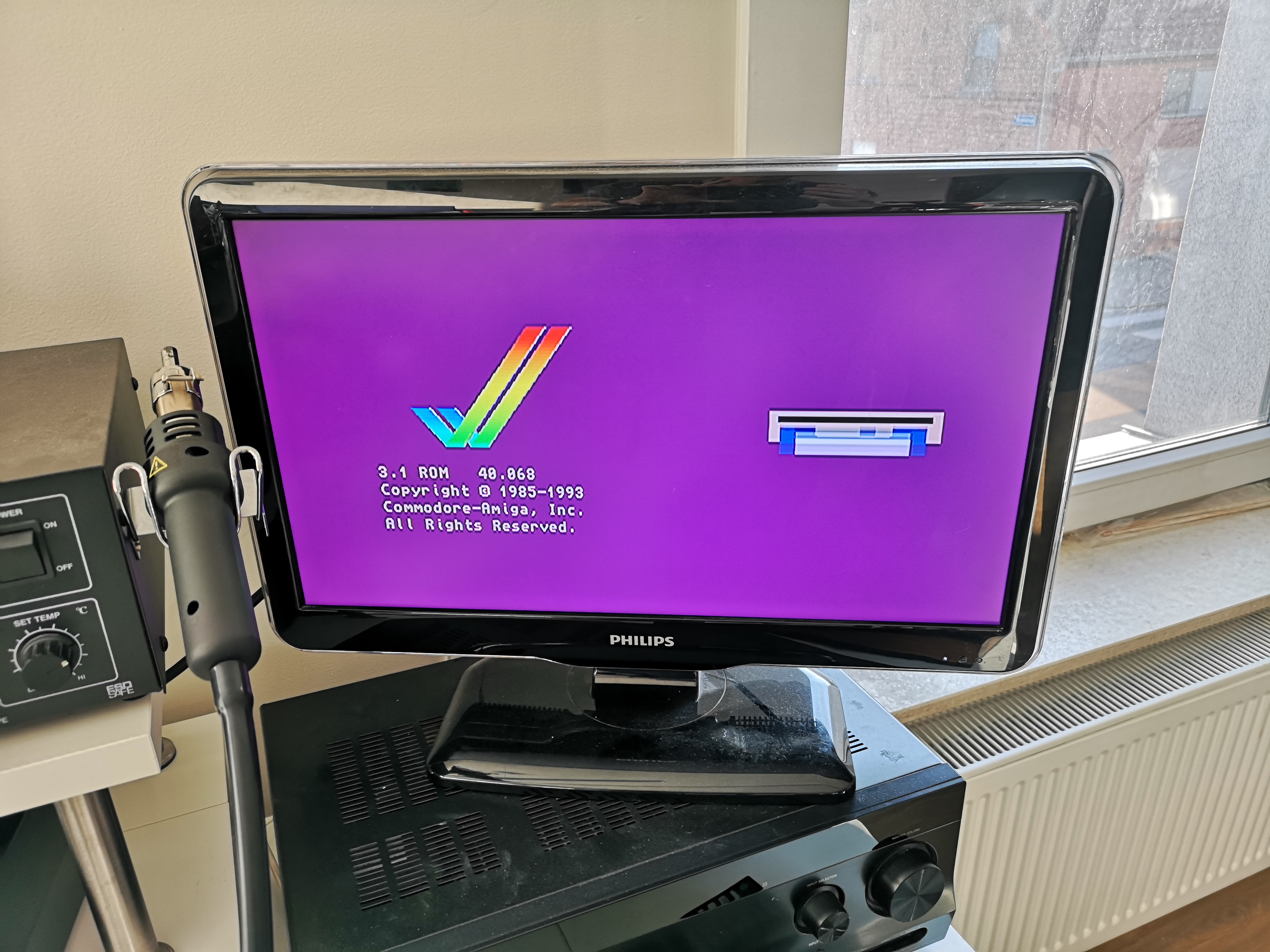
Kickstart produces picture!
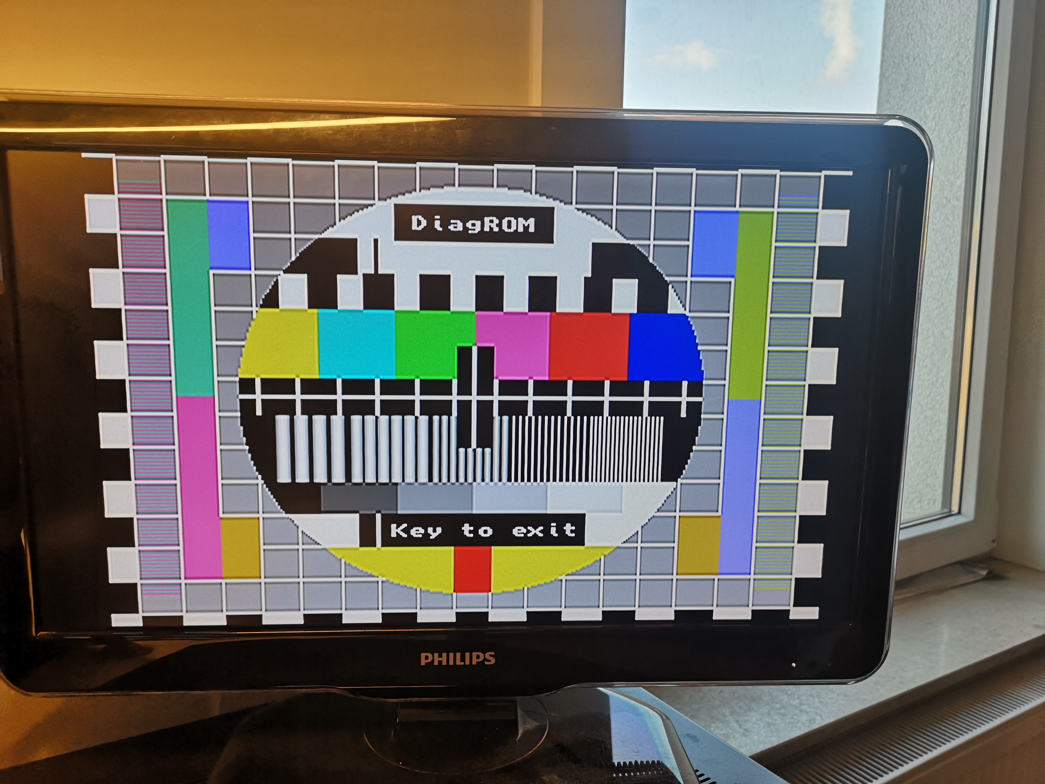
Video out in DiagRom
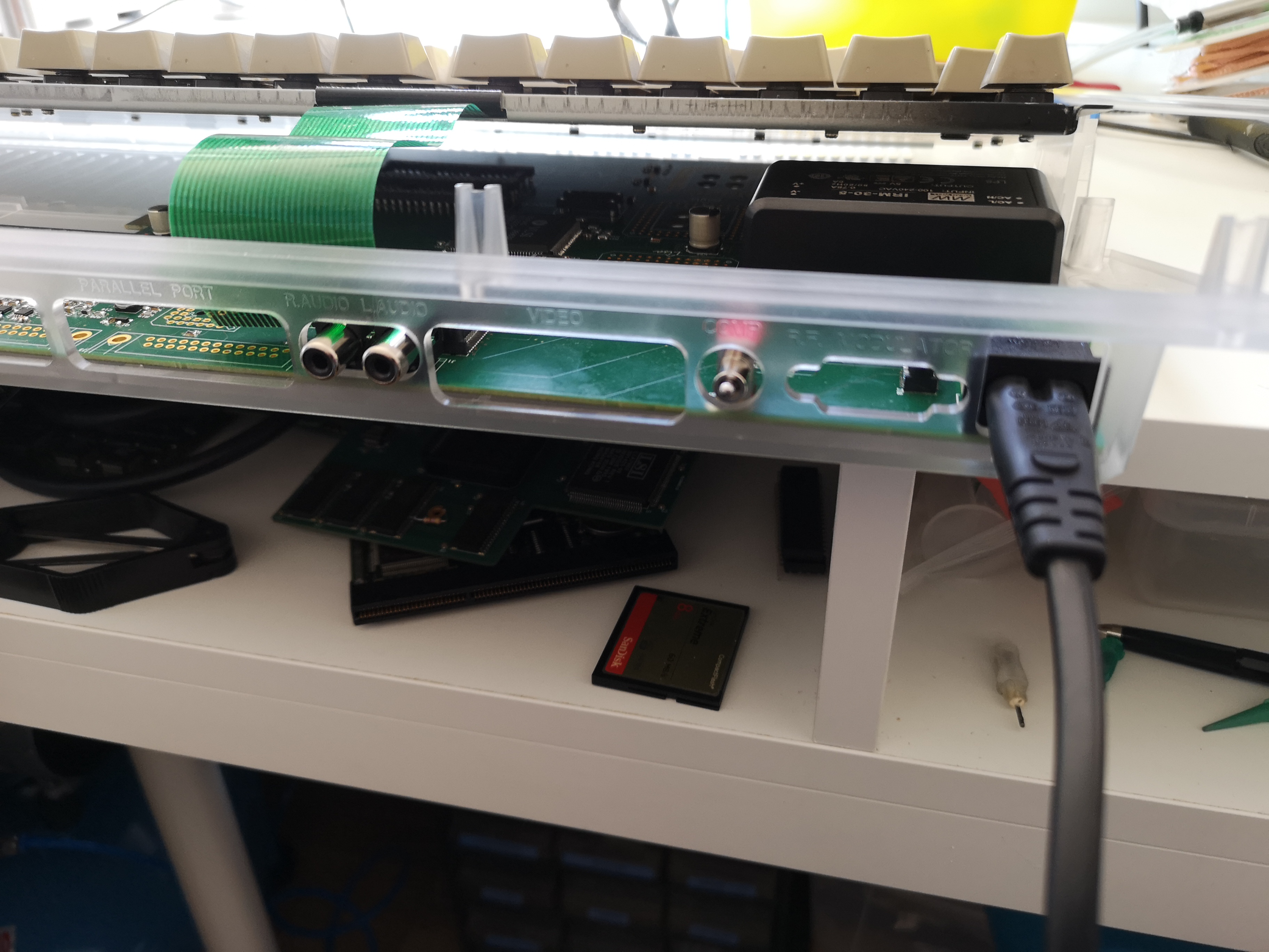
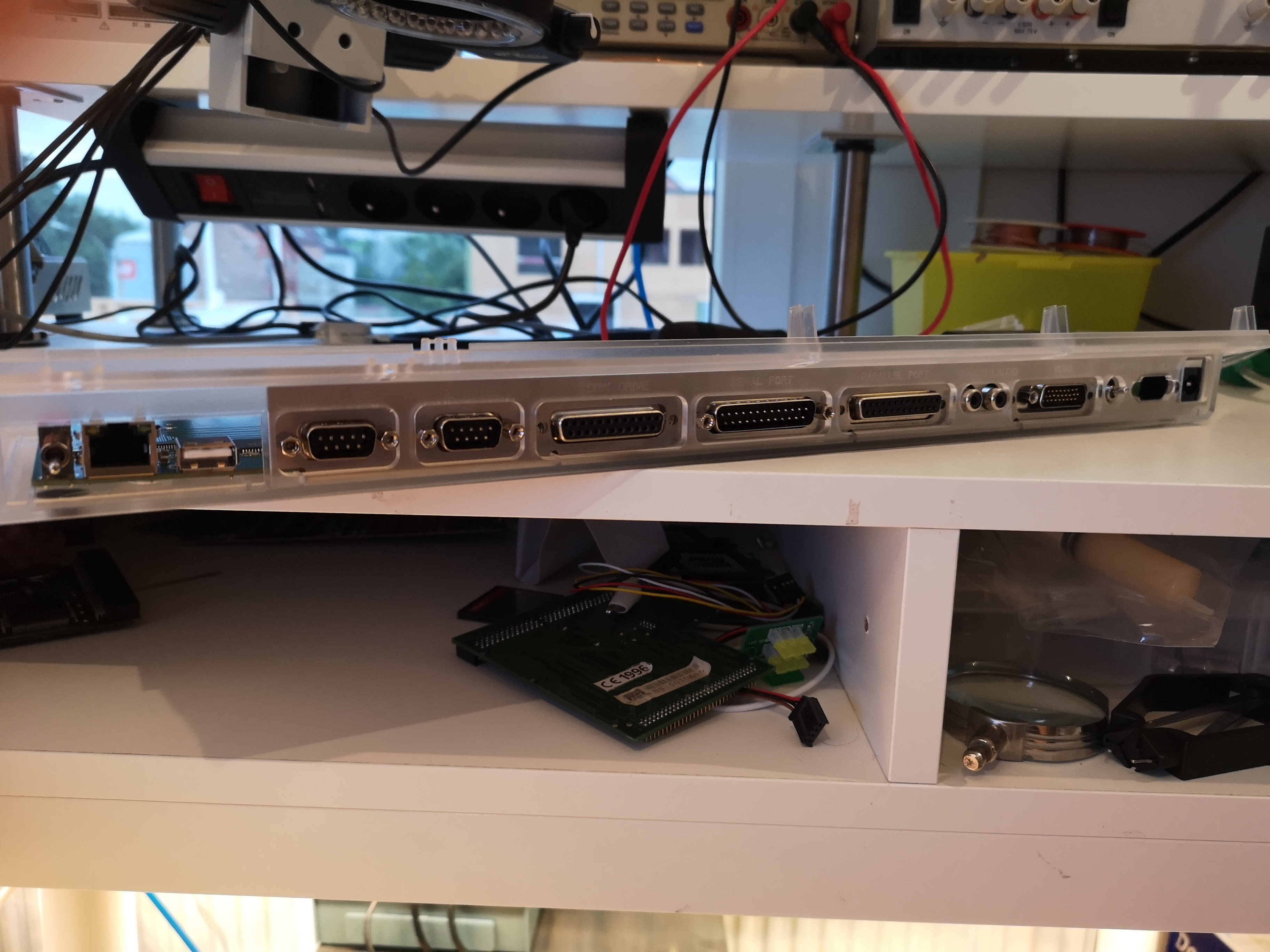
This is the backside of the A1200+
from left to right:
- Boot Selector
- Ethernet
- USB Mouse using SmallyMouse2
- Joystick 1
- Joystick 2
- External Disk drive
- Serial Port
- Parallel Port
- Audio
- Video Out
- On/Off switch
- Mains power inlet
All the PCBs together.
Rev1
Rev 1 PCB, hopefully, this one will give me some screen output...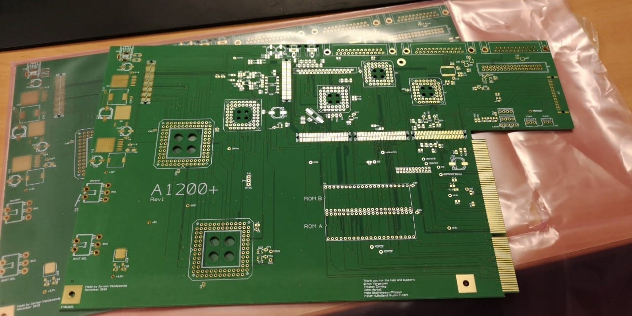
May 2019
Booting Kickstart for the first time.
The colors are a bit off but still: HUGE step. Hooray!
A bug in the RGB bus is causing the colors to be off.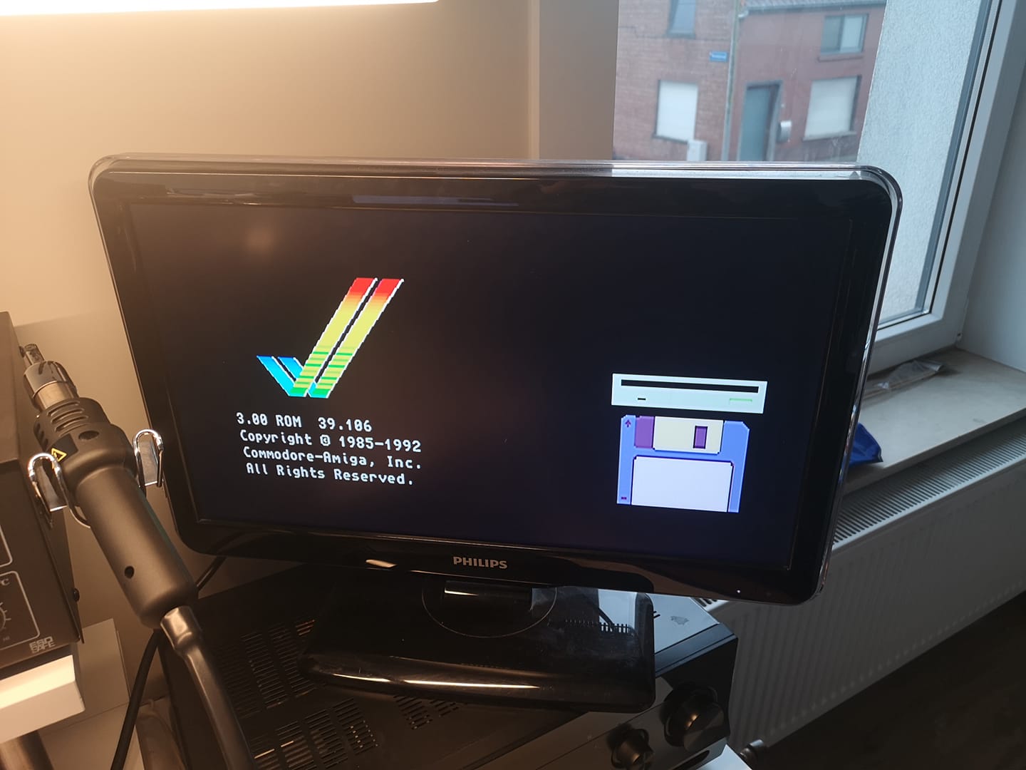
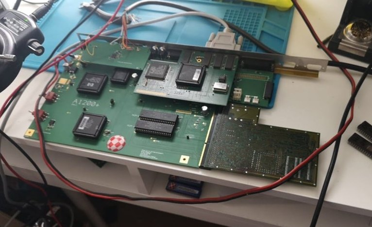
All the PCBs put together.
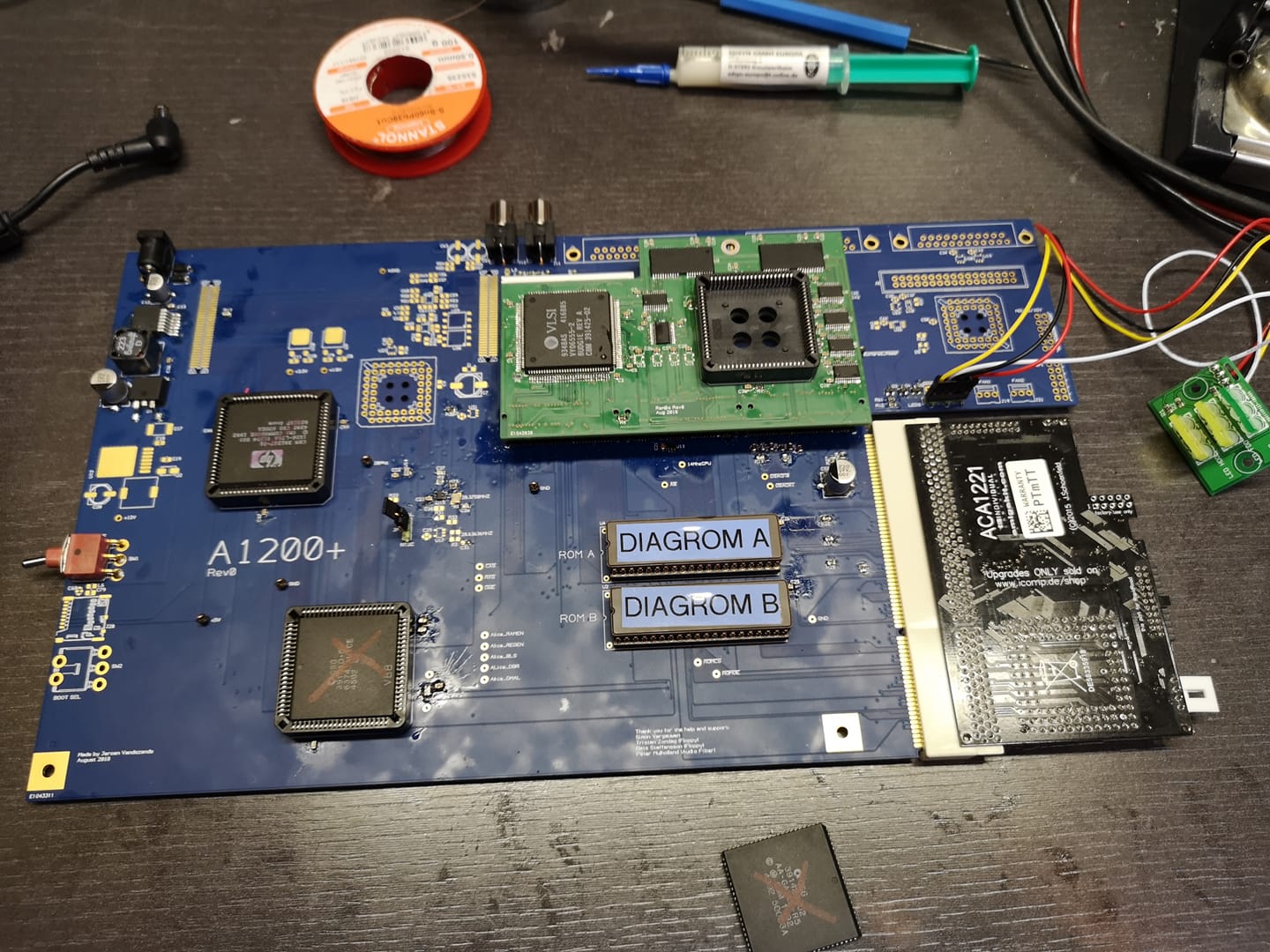
Rev0
This is a rendering of the rev0 pcb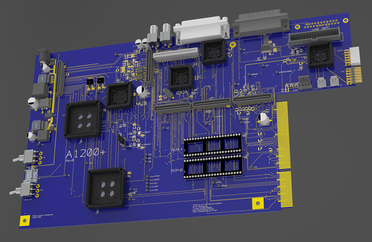
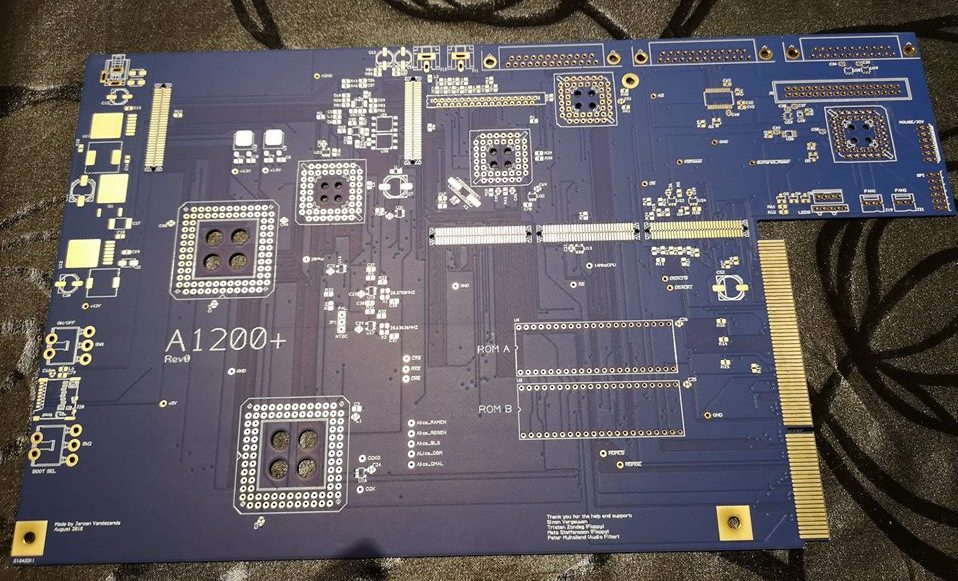
And some pictures of the real Rev0 pcb!
The Ram Board has arrived, soon will start populating that one...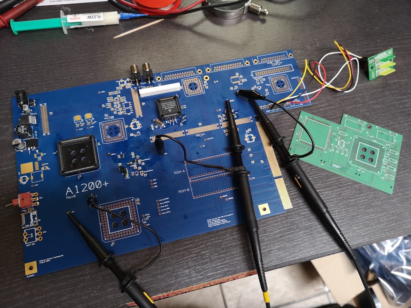
Power-on reset of the keyboard controller and reset lines all over the board are working fine... I made sure that the reset was hold low for at least 450 ms.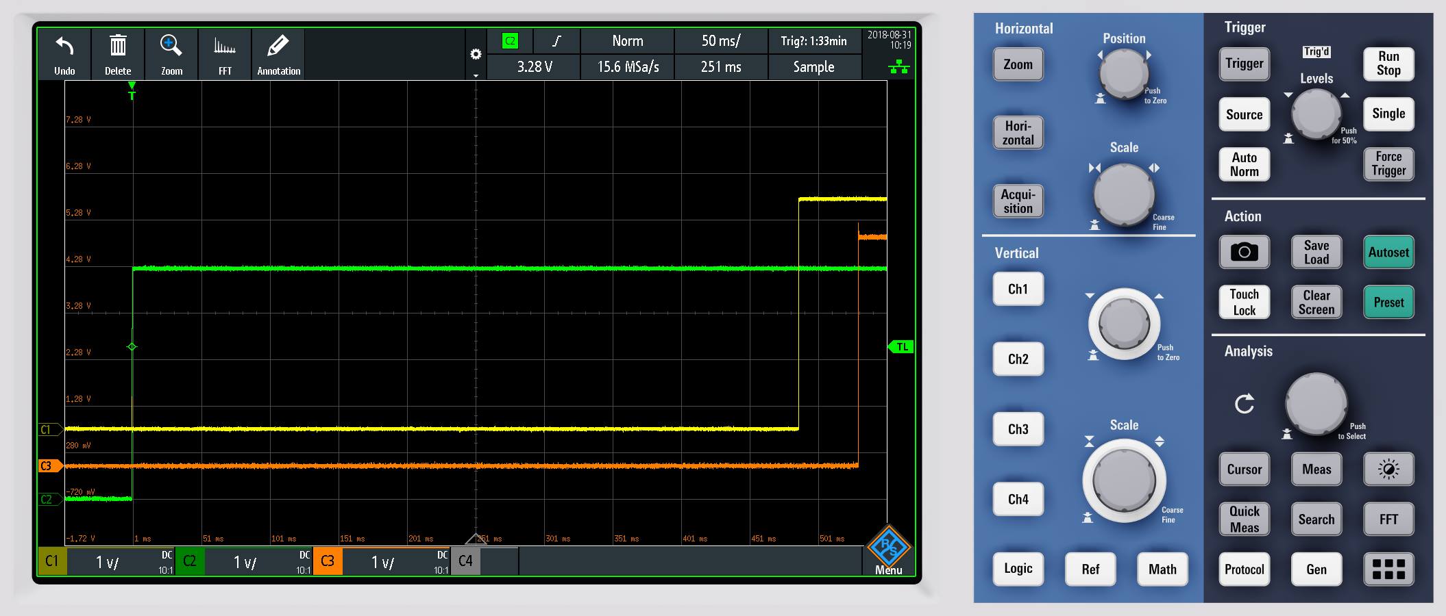
Here is a picture of the connector on the bottom of the RamBoard and one on the main board... there will be 3 of those in a row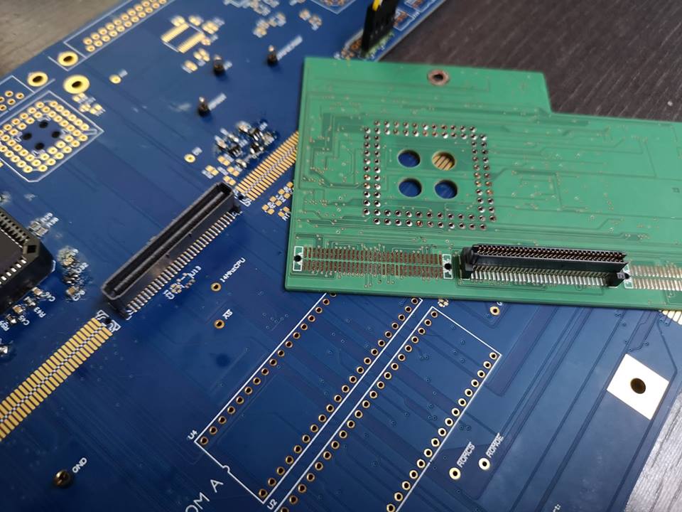
Finished Test RamBoard ... and it fits on the mainboard!